 New Mould


 Plastic Products


 Feature Service
Mould Equipment
Feature Service
Mould Equipment
Mold & Die Knowlege
Mold
Mold or die are the common terms used to describe the tooling used to produce plastic parts in molding.
Traditionally, molds have been expensive to manufacture. They were usually only used in mass production where thousands of parts were being produced. Molds are typically constructed from hardened steel, pre-hardened steel, aluminium, and/or beryllium-copper alloy. The choice of material to build a mold from is primarily one of economics, steel molds generally cost more to construct, but their longer lifespan will offset the higher initial cost over a higher number of parts made before wearing out. Pre-hardened steel molds are less wear resistant and are used for lower volume requirements or larger components. The steel hardness is typically 38-45 on the Rockwell-C scale. Hardened steel molds are heat treated after machining. These are by far the superior in terms of wear resistance and lifespan. Typical hardness ranges between 50 and 60 Rockwell-C (HRC). Aluminium molds can cost substantially less, and when designed and machined with modern computerized equipment, can be economical for molding tens or even hundreds of thousands of parts. Beryllium copper is used in areas of the mold which require fast heat removal or areas that see the most shear heat generated. The molds can be manufactured by either CNC machining or by using Electrical Discharge Machining processes
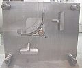
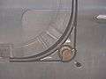
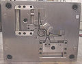
| Injection molding die with side pulls | |||
 |
 |
 |
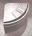 |
| "A" side of die for 25% glass-filled acetal with 2 side pulls. | Close up of removable insert in "A" side. | "B" side of die with side pull actuators. | Insert removed from die. |
Mold Design
Molds separate into two sides at a parting line, the A side, and the B side, to permit the part to be extracted. Plastic resin enters the mold through a sprue in the A plate, branches out between the two sides through channels called runners, and enters each part cavity through one or more specialized gates. Inside each cavity, the resin flows around protrusions (called cores) and conforms to the cavity geometry to form the desired part. This is similar to someone squeezing clay between their hands so that when it is removed, it matches the shape of the hollow of their cupped hands.
The amount of resin required to fill the sprue, runner and cavities of a mold is a shot. When a core shuts off against an opposing mold cavity or core, a hole results in the part. Air in the cavities when the mold closes escapes through very slight gaps between the plates and pins, into shallow plenums called vents. To permit removal of the part, its features must not overhang one another in the direction that the mold opens, unless parts of the mold are designed to move from between such overhangs when the mold opens (utilizing components called Lifters).
Sides of the part that appear parallel with the direction of draw (the direction in which the core and cavity separate from each other) are typically angled slightly with (draft) to ease release of the part from the mold, and examination of most plastic household objects will reveal this. Parts with bucket-like features tend to shrink onto the cores that form them while cooling, and cling to those cores when the cavity is pulled away. The mold is usually designed so that the molded part reliably remains on the ejector (B) side of the mold when it opens, and draws the runner and the sprue out of the (A) side along with the parts. The part then falls freely when ejected from the (B) side. Tunnel gates tunnel sharply below the parting surface of the B side at the tip of each runner so that the gate is sheared off of the part when both are ejected.
Ejector pins are the most popular method for removing the part from the B side core(s), but air ejection, and stripper plates can also be used depending on the application. Most ejection plates are found on the moving half of the tool, but they can be placed on the fixed half if spring loaded. For thermoplastics, coolant, usually water with corrosion inhibitors, circulates through passageways bored through the main plates on both sides of the mold to enable temperature control and rapid part solidification.
To ease maintenance and venting, cavities and cores are divided into pieces, called inserts, and sub-assemblies, also called inserts, blocks, or chase blocks. By substituting interchangeable inserts, one mold may make several variations of the same part.
More complex parts are formed using more complex molds. These may have sections called slides, that move into a cavity perpendicular to the draw direction, to form overhanging part features. Slides are then withdrawn to allow the part to be released when the mold opens. Slides are typically guided and retained between rails called gibs, and are moved when the mold opens and closes by angled rods called horn pins and locked in place by locking blocks, both of which move cross the mold from the opposite side.
Some molds allow previously molded parts to be reinserted to allow a new plastic layer to form around the first part. This is often referred to as overmolding. This system can allow for production of one-piece tires and wheels.
2-shot or multi-shot molds are designed to "overmold" within a single molding cycle and must be processed on specialized injection molding machines with two or more injection units. This can be achieved by having pairs of identical cores and pairs of different cavities within the mold. After injection of the first material, the component is rotated on the core from the one cavity to another. The second cavity differs from the first in that the detail for the second material is included. The second material is then injected into the additional cavity detail before the completed part is ejected from the mold. Common applications include "soft-grip" toothbrushes and freelander grab handles.
The core and cavity, along with injection and cooling hoses form the mold tool. While large tools are very heavy weighing hundreds and sometimes thousands of pounds, with the aid of a forklift or overhead crane, they can be hoisted into molding machines for production and removed when molding is complete or the tool needs repairing.
A mold can produce several copies of the same parts in a single "shot". The number of "impressions" in the mold of that part is often incorrectly referred to as cavitation. A tool with one impression will often be called a single cavity (impression) tool. A mold with 2 or more cavities of the same parts will likely be referred to as multiple cavity tooling. Some extremely high production volume molds (like those for bottle caps) can have over 128 cavities.
In some cases multiple cavity tooling will mold a series of different parts in the same tool. Some toolmakers call these molds family molds as all the parts.
Effects on the material properties
The mechanical properties of a part are usually little effected. Some parts can have internal stresses in them. This is one of the reasons why it's good to have uniform wall thickness when molding. One of the physical property changes is shrinkage. A permanent chemical property change is the material thermoset, which can't be remelted to be injected again.
The effects on work material properties is best illustrated by the table below from Manufacturing Processes Reference Guide:
| Work Material Properties | Effects of Injection Molding |
| Mechanical | Plastic components may develop internal stress |
| Physical | Permanent shrinkage at elevated temperatures |
| Chemical | Thermoset materials cannot be remelted |
Tool Materials
Tool steel or beryllium-copper are often used. Mild steel, aluminum, nickel or epoxy are only suitable for prototype or very short production runs.
Geometrical Possibilities
The most commonly used plastic molding process, injection molding, is used to create a large variety of products with different shapes and sizes. Most importantly, they can create products with complex geometry that many other processes cannot. There are a few precautions when designing something that will be made using this process to reduce the risk of weak spots. First, streamline your product or keep the thickness relatively uniform. Second, try and keep your product between 2 to 20 inches.
The size of a part will depend on a number of factors (material, wall thickness, shape,process ect). The initial raw material required may be measured in the form of granules, pellets or powders. Here are some ranges of the sizes.
| Method | Raw Materials | Maximum Size | Minimum Size |
| Injection Molding (thermo-plastic) | Granules, Pellets, Powders | 700 oz. | Less than 1 oz. |
| Injection Molding (thermo-setting) | Granules, Pellets, Powders | 200 oz. | Less Than 1 oz. |
Machining
Molds are built through two main methods: standard machining and EDM. Standard Machining, in its conventional form, has historically been the method of building injection molds. With technological development, CNC machining became the predominant means of making more complex molds with more accurate mold details in less time than traditional methods.
The electrical discharge machining (EDM) or spark erosion process has become widely used in mold making. As well as allowing the formation of shapes which are difficult to machine, the process allows pre-hardened molds to be shaped so that no heat treatment is required. Changes to a hardened mold by conventional drilling and milling normally require annealing to soften the steel, followed by heat treatment to harden it again. EDM is a simple process in which a shaped electrode, usually made of copper or graphite, is very slowly lowered onto the mold surface (over a period of many hours), which is immersed in paraffin oil. A voltage applied between tool and mold causes spark erosion of the mold surface in the inverse shape of the electrode.
Cost
The cost of manufacturing molds depends on a very large set of factors ranging from number of cavities, size of the parts (and therefore the mold), complexity of the pieces, expected tool longevity, surface finishes and many others. The initial cost is great, however the piece part cost is low, so with greater quantities the overall price decreases.
Injection process
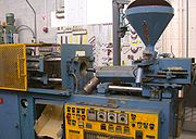
Small injection molder showing hopper, nozzle and die area
For detailed explanation refer below to "Injection Molding Cycle".
With Injection Molding, granular plastic is fed by gravity from a hopper into a heated barrel. As the granules are slowly moved forward by a screw-type plunger, the plastic is forced into a heated chamber, where it is melted. As the plunger advances, the melted plastic is forced through a nozzle that rests against the mold, allowing it to enter the mold cavity through a gate and runner system. The mold remains cold so the plastic solidifies almost as soon as the mold is filled.
Injection molding cycle
For the injection molding cycle to begin, four criteria must be met: mold open, ejector pins retracted, shot built, and carriage forward. When these criteria are met, the cycle begins with the mold closing. This is typically done as fast as possible with a slow down near the end of travel. Mold safety is low speed and low pressure mold closing. It usually begins just before the leader pins of the mold and must be set properly to prevent accidental mold damage. When the mold halves touch clamp tonnage is built. Next, molten plastic material is injected into the mold. The material travels into the mold via the sprue bushing, then the runner system delivers the material to the gate. The gate directs the material into the mold cavity to form the desired part. This injection usually occurs under velocity control.
When the part is nearly full, injection control is switched from velocity control to pressure control. This is referred to as the pack/hold phase of the cycle. Pressure must be maintained on the material until the gate solidifies to prevent material from flowing back out of the cavity. Cooling time is dependent primarily on the wall thickness of the part but also depends on the material being molded. Production molding usually requires faster cooling. Water is often channeled throughout the dies to produce faster cooling times. During the cooling portion of the cycle after the gate has solidified, plastication takes place.
Plastication is the process of melting material and preparing the next shot. The material begins in the hopper and enters the barrel through the feed throat. The feed throat must be cooled to prevent plastic pellets from fusing together from the barrel heat. The barrel contains a screw that primarily uses shear to melt the pellets and consists of three sections. The first section is the feed section which conveys the pellets forward and allows barrel heat to soften the pellets. The flight depth is uniform and deepest in this section. The next section is the transition section and is responsible for melting the material through shear. The flight depth continuously decreases in this section, compressing the material. The final section is the metering section which features a shallow flight depth, improves the melt quality and color dispersion. At the front of the screw is the non-return valve which allows the screw to act as both an extruder and a plunger. When the screw is moving backwards to build a shot, the non-return assembly allows material to flow in front of the screw creating a melt pool or shot. During injection, the non-return assembly prevents the shot from flowing back into the screw sections.
Once the shot has been built and the cooling time has timed out, the mold opens. Mold opening must occur slow-fast-slow. The mold must be opened slowly to release the vacuum that is caused by the injection molding process and prevent the part from staying on the stationary mold half. This is undesirable because the ejection system is on the moving mold half. Then the mold is opened as far as needed, if robots are not being used, the mold only has to open far enough for the part to be removed. A slowdown near the end of travel must be utilized to compensate for the momentum of the mold. Without slowing down the machine cannot maintain accurate positions and may slam to a stop damaging the machine. Once the mold is open, the ejector pins are moved forward, ejecting the part. When the ejector pins retract, all criteria for a molding cycle have been met and the next cycle can begin.
The basic injection cycle is as follows: Mold close – injection carriage forward – inject plastic – metering – carriage retract – mold open – eject part(s) Some machines are run by electric motors instead of hydraulics or a combination of both. The water-cooling channels that assist in cooling the mold and the heated plastic solidifies into the part. Improper cooling can result in distorted molding. The cycle is completed when the mold opens and the part is ejected with the assistance of ejector pins within the mold.
The resin, or raw material for injection molding, is most commonly supplied in pellet or granule form. Resin pellets are poured into the feed hopper, a large open bottomed container, which is attached to the back end of a cylindrical, horizontal barrel. A screw within this barrel is rotated by a motor, feeding pellets up the screw's grooves. The depth of the screw flights decreases toward the end of the screw nearest the mold, compressing the heated plastic. As the screw rotates, the pellets are moved forward in the screw and they undergo extreme pressure and friction which generates most of the heat needed to melt the pellets. Electric heater bands attached to the outside of the barrel assist in the heating and temperature control during the melting process.
The channels through which the plastic flows toward the chamber will also solidify, forming an attached frame. This frame is composed of the sprue, which is the main channel from the reservoir of molten resin, parallel with the direction of draw, and runners, which are perpendicular to the direction of draw, and are used to convey molten resin to the gate(s), or point(s) of injection. The sprue and runner system can be cut or twisted off and recycled, sometimes being granulated next to the mold machine. Some molds are designed so that the part is automatically stripped through action of the mold.
Time Function
| The time it takes to make a product using injection molding can be calculated by adding: Twice the Mold Open/Close Time (2M) + Injection Time (T) + Cooling Time (C) + Ejection Time (E) Where T is found by dividing: Mold Size (S) / Flow Rate (F) Total time = 2M + T + C + E T = V/R V = Mold cavity size (in3) R = Material flow rate (in3/min) |
http://upload.wikimedia.org/wikipedia/commons/9/9e/Time_Calculation.jpg
Molding trial
When filling a new or unfamiliar mold for the first time, where shot size for that mold is unknown, a technician/tool setter usually starts with a small shot weight and fills gradually until the mold is 95 to 99% full. Once this is achieved a small amount of holding pressure will be applied and holding time increased until gate freeze off has occurred, then holding pressure is increased until the parts are free of sinks and part weight has been achieved. Once the parts are good enough and have passed any specific criteria, a setting sheet is produced for people to follow in the future.
Process optimization is done using the following methods. Injection speeds are usually determined by performing viscosity curves. Process windows are performed varying the melt temperatures and holding pressures. Pressure drop studies are done to check if the machine has enough pressure to move the screw at the set rate. Gate seal or gate freeze studies are done to optimize the holding time. A cooling time study is done to optimize the cooling time.
Molding defects
Injection molding is a complex technology with possible production problems. They can either be caused by defects in the molds or more often by part processing (molding)
| Molding Defects | Alternative name | Descriptions | Causes |
| Blister | Blistering | Raised or layered zone on surface of the part | Tool or material is too hot, often caused by a lack of cooling around the tool or a faulty heater |
| Burn marks | Air Burn/ Gas Burn | Black or brown burnt areas on the part located at furthest points from gate | Tool lacks venting, injection speed is too high |
| Color streaks (US) | Colour streaks (UK) | Localized change of color/colour | Masterbatch isn't mixing properly, or the material has run out and it's starting to come through as natural only |
| Delamination | Thin mica like layers formed in part wall | Contamination of the material e.g. PP mixed with ABS, very dangerous if the part is being used for a safety critical application as the material has very little strength when delaminated as the materials cannot bond | |
| Flash | Burrs | Excess material in thin layer exceeding normal part geometry | Tool damage, too much injection speed/material injected, clamping force too low. Can also be caused by dirt and contaminants around tooling surfaces. |
| Embedded contaminates | Embedded particulates | Foreign particle (burnt material or other) embedded in the part | Particles on the tool surface, contaminated material or foreign debris in the barrel, or too much shear heat burning the material prior to injection |
| Flow marks | Flow lines | Directionally "off tone" wavy lines or patterns | Injection speeds too slow (the plastic has cooled down too much during injection, injection speeds must be set as fast as you can get away with at all times) |
| Jetting | Deformed part by turbulent flow of material | Poor tool design, gate position or runner. Injection speed set too high. | |
| Polymer degradation | polymer breakdown from hydrolysis, oxidation etc | Excess water in the granules, excessive temperatures in barrel | |
| Sink marks | Localized depression (In thicker zones) | Holding time/pressure too low, cooling time too short, with sprueless hot runners this can also be caused by the gate temperature being set too high | |
| Short shot | Non-fill / Short mold | Partial part | Lack of material, injection speed or pressure too low |
| Splay marks | Splash mark / Silver streaks | Circular pattern around gate caused by hot gas | Moisture in the material, usually when hygroscopic resins are dried improperly |
| Stringiness | Stringing | String like remain from previous shot transfer in new shot | Nozzle temperature too high. Gate hasn't frozen off |
| Voids | Empty space within part (Air pocket) | Lack of holding pressure (holding pressure is used to pack out the part during the holding time). Also mold may be out of registration (when the two halves don't center properly and part walls are not the same thickness) | |
| Weld line | Knit line / Meld line | Discolored line where two flow fronts meet | Mold/material temperatures set too low (the material is cold when they meet, so they don't bond) |
| Warping | Twisting | Distorted part | Cooling is too short, material is too hot, lack of cooling around the tool, incorrect water temperatures (the parts bow inwards towards the hot side of the tool) |
Tolerances and Surfaces
Injection molding typically is capable of tolerances equivalent to an IT Grade of about 9–14. The possible tolerance of a thermoplastic or a thermoset is +/-0.008 to +/-0.002 inches. Surface finishes of two to four microinches or better are can be obtained. Rough or pebbled surfaces are also possible
| Molding Type | Typical | Possible |
| Thermoplastic | ±0.008 | ±0.002 |
| Thermoset | ±0.008 | ±0.002 |

